Getting Started with the ControlBlock
Getting Started with the ControlBlock
The hardware and software setup of the ControlBlock is done in only a few steps. You find all necessary information for making your project run wit the ControlBlock on this page.
Getting Started at a Glance
- Attach a toggle or momentary power switch
- Optionally, attach a status LED
- Mount the ControlBlock on the Raspberry Pi
- Attach a power supply
- Connect controllers
- Install the ControlBlock driver

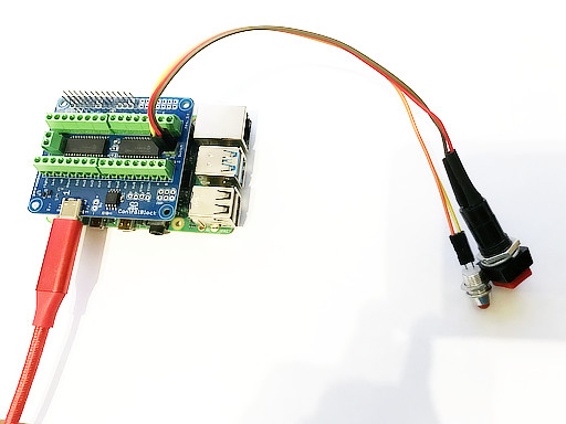
1. Attach a toggle or momentary button
To turn the Raspberry Pi on and off with the ControlBlock you need to attach a button to the two pins labeled with “switch”.
You can use a toggle or a momentary button. The type of button is detected automatically by the ControlBlock.
If you do not want to use the power switch functionality you can disable this in the configuration file /etc/controlblockconfig.cfg by setting “powerswitch”: false.
A good quality power supply and a good quality USB cable are mandatory for a working setup. If unsure, we can recommend the official Raspberry Pi Power Supply.+
2. Optionally, attach a status LED
The ControlBlock has pin outs for an optional status LED that indicates the power state of the Raspberry Pi. You can directly attach an LED to the pins that are marked with “LED”. You need to pay attention to the polarity of the LED: The LED pins are marked with “+” and “-” for that.
The LED will blink in four different patterns that depend on the power state of the Raspberry Pi:
- Off: The LED is simply off.
- Booting: The LED slowly fades in and out.
- On: The LED constantly stays on.
- Shutting down: The LED fades in and out twice as fast as during boot up.
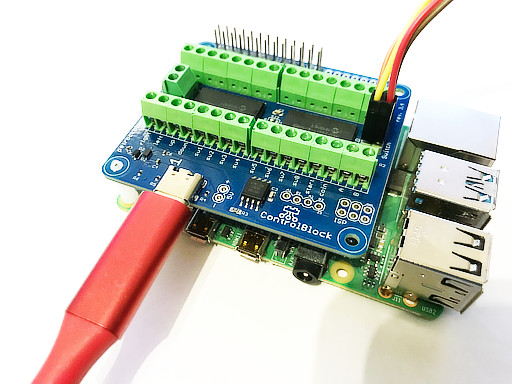
3. Mount the ControlBlock
To attach the ControlBlock, mount locking posts first. Then attach the ControlBlock
4. Attach a Power Supply
If you want to use the power switch function of the ControlBlock you need to connect your USB-C cable only to the ControlBlock – and not to the Raspberry Pi directly. Also, you could use the 5V and GND input pins for power supply.
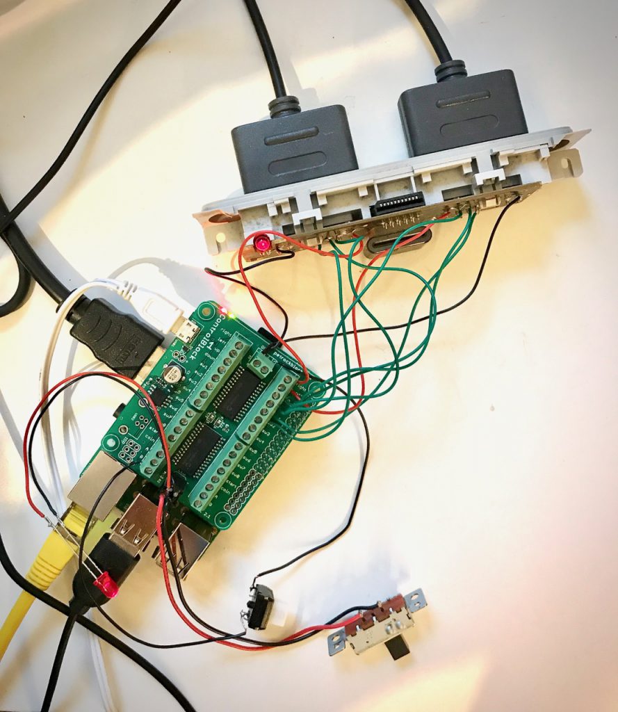
5. Connect Controllers
To run the quick installation, you just need to call this one line from the Raspbian console:
wget -O - https://raw.githubusercontent.com/petrockblog/ControlBlockService2/master/install.sh | sudo bash
To uninstall the service you can simply call sudo ./uninstall.sh from within the controlblockservice2 directory.
More information can be found on the driver’s website.
6. Install the ControlBlock driver
If you want to use the power switch function of the ControlBlock you need to connect your USB-C cable only to the ControlBlock – and not to the Raspberry Pi directly. Also, you could use the 5V and GND input pins for power supply.
And that’s it
The ControlBlock should do its job now.
Information about configuration possibilities, logging, and custom shutdown scripts can be found on the driver’s page.
You can also find further information in our forum.